When I last left off, I had finished the escape bridge jewel conversion. Since the conversion was successful, the next step was doing a conversion on the main plate for the bottom of the escape wheel. All my measurements that I did on Thursday (the pivot width, jewel size, etc) carried over for the plate, so I used another 11/90 jewel (.11 mm diameter inner hole/.90 mm diameter jewel). The process for doing the conversion was exactly the same. I broached the hole, ensuring that I got the hole centered properly. I stopped frequently to check my work as well as deburring as I went. I used the same reaming attachment for the jeweling tool (.89 mm).
After I got the hole reamed, I got the jewel pressed in and replaced the escape wheel and bridge. The wheel spun, but not very freely. I took it up to Mr. Poye to get his advice and he recommended that I check the end-shake. When I went back to my desk, I checked the end-shake and found out that I had none. Instead of adjusting the depth of both jewels, I decided to only change one variable, check it and adjust as needed. The first couple of times I got a bit too much depth/end-shake, but after a few tries I was able to dial it in. I had to add a little bit of depth to the bridge, but not too much. Once I got the bridge screwed down, I checked the wheel for end-shake and spin and everything looked great. I went ahead and put the rest of the gears in and double checked my work, and it looked good.
After I got done with that, it was time for me to start my final jeweling project.
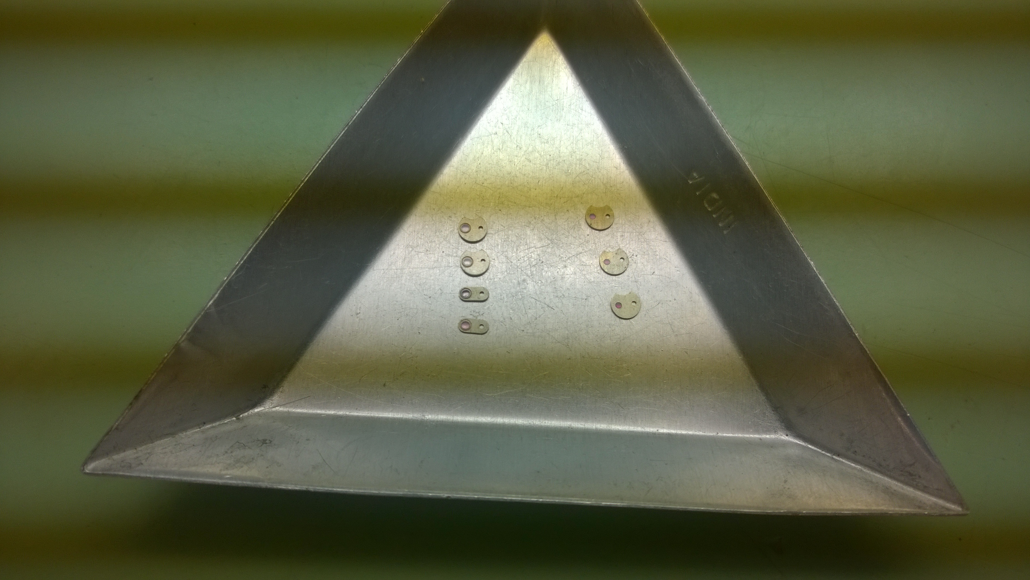
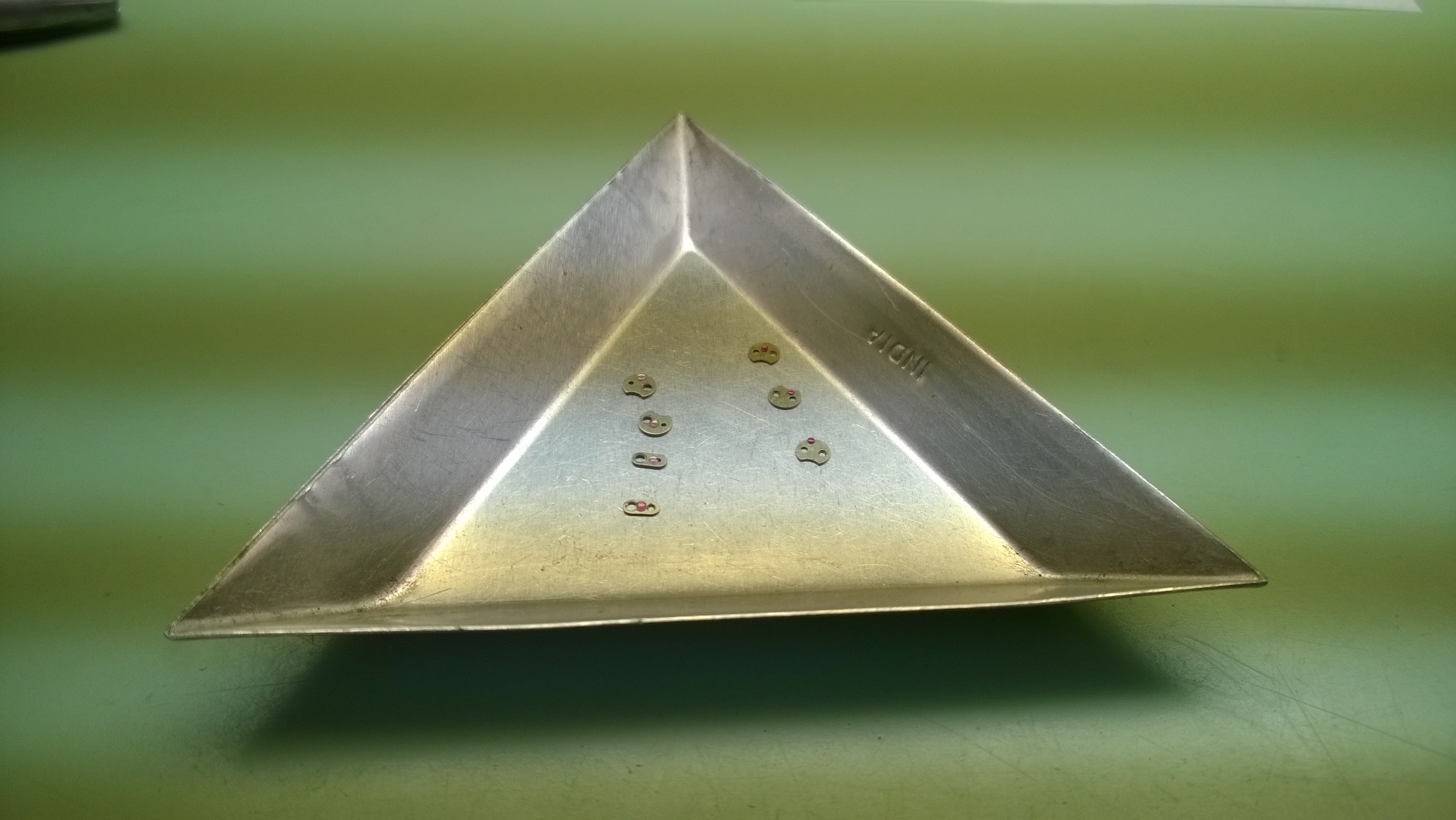
In the above picture, there are 7 different kinds of cap jewels. Usually, if there is a crack or something with a cap jewel, you just replace it and move on with your job. While working with cap jewels is, in theory no different than any of the other friction fit jewels-press them out on the curved side (in this case, the curve would be analogous to the oil sink) and in on the flat side (the curved side has the bevel on it). Take another look at the jewels. The ones on the right are normal, friction fit jewels. The ones on the left are also friction fit, but they have a bezel that holds them in place. Once they get pressed back in, the bezel needs to be burnished back over the jewel.
 Getting them out was relatively easy. Putting the back in, well, let me just say that I think this project was designed to encourage/teach proper use of the micrometer stop. After all the work I did with the friction jewels to this point made me a bit over-confident. I ended up cracking my first two jewels that I tried to put back in. After getting a couple of replacements, I went a lot slower and really took advantage of the micrometer adjustment. The process I used for this was as follows:
- Select the stump and punch needed for pressing the jewel flush.
- Lower the punch until it was just touching the plate/cap and make a note of the measurement on the micrometer
- Raise the punch a few tenths on the micrometer and place the jewel in the cap/plate
- Lower the punch until it is just a tenth above the original measurement and slowly turn the micrometer to lower the punch and friction the jewel in its place.
Once I got that process down, I was able to get the rest of the jewels put in with no issue. For burnishing the bezel, I used a round faced staking punch.
Once I got done with that project, I moved on to learning about replacing regulator keys.
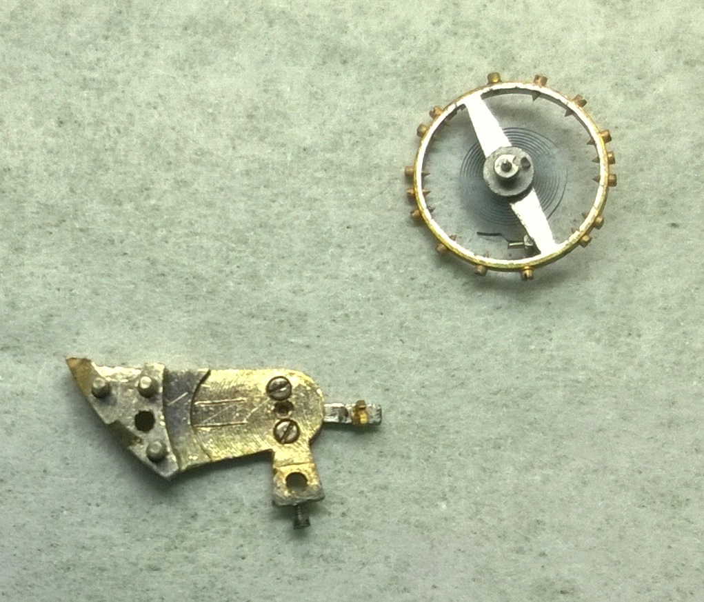 On the balance bridge, the regulator arm is the one pointing out to the right. The brass part is the regulator key. In about 95% of watches, the regulator key swings open and close.
 If you click on the picture, the regulator arm is the one with two rivets on it. The rivet on the outside is the one for the regulator key (I am just going to call it a key from now on).
 When replacing a key, there are a few things that you need to match up for the new key:
- Height of the key
- Width of the toe (the long part of the key that forms the “L” shape at the bottom)
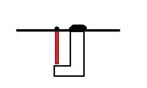
- Width of the key body (if the space between the key and the regulator pin (the red part) is too large or too narrow, the hairspring will not move through it properly.
The process for removing the key is simple-use an escapement file, remove the rivet and press the key out. Easier said than done. I have found that I can usually get most of the rivet off without scratching the regulator arm. Since I had a couple scratches, I used the emery paper from when I did the pallet fork pins and got rid of the scratches.
Once you find the right replacement key, you slide it in and create the rivet with a riveting hammer (a very nice polish on a slanted head for the hammer). Again, easier said than done. I’ll put up pictures on Saturday, but if you remember the boxes of jewels that I had to search for when working with pallet forks-it was like that. Except this time, it was a pile of regulators, and three boxes of keys.
I should be finished with this project tomorrow, and if I am, I get to move on to my new section: 16-Point Check System.
